For the first time in the history of sound reproduction an audio amplifier has won world-wide recognition by its pre-eminence in performance, reliability and craftsmanship. In this booklet the designer of the two units comprising the amplifier describes them in a manner acceptable both to the professional communications engineer and to the amateur enthusiast seeking the highest available standard of sound reproduction.
The information contained herein is factual, and of necessity brief. For those who would like more detailed explanations than our space allows, superscript references are made to well-known text books and journals, these being listed on page 24.
" POINT ONE "* is the Trade Mark of H. J. Leak & Co., Ltd. It was originally applied to the first power amplifiers having a total distortion as low as point one of one per cent, when in June, 1945 H. J. Leak, M.Brit.I.R.E., revolutionised the performance standards for audio amplifiers by designing the original "POINT ONE" series.
* T.M. Reg. U.S. Pat. Off.
TEST CONDlTIONS.
In all cases the input was applied to a 50,000 ohm resistor connected to the amplifier by 3 feet of screened cable. The output load was in all cases a resistor of 18 ohms, and the output transformer secondary windings were connected for the " 15 ohms-20 ohms" condition.
TOTAL HARMONIC DISTORTION for 10 WATTS OUTPUT.
0.037 at 1,000 c/s, (0.0003 ratio to fundamental).
0.1% at 60 c/s, (0.001 ratio to fundamental).
2nd and 3rd harmonics predominated, and were approximately equal in magnitude.
HUM AND NOISE.
-80db referred to 10 watts.
SENSITIVITY.
148mV r.m.s. input gave 12 watts output at 1,000 c/s.
LOAD DAMPING FACTOR. (Load impedance/output impedance).
42 for 10 watts output at 1,000 c/s. (Output impedance
0.43 ohms).
45 for 2.5 watts output at 1,000 c/s. (Output impedance 0.40 ohms).
The output impedance was found to be substantially resistive.
FREQUENCY RESPONSE.
Gain relative to that at 1,000 c/s measured at 7.5 watts output, including the losses introduced at the higher frequencies by the capacitance of the input resistance of 50,000 Ohms.
c/s |
db |
|---|---|
| 20 | +0.1 |
| 60 to 1000 | 0.0 |
| 5,000 | - 0.1 |
| 10,000 | -0.3 |
| 15,000 | -0.4 |
| 20,000 | -0.7 |
| Date: 30th August, 1949. | C. G. DARWIN, Director. |
| Reference: E.388. 150. | L. HARTSHORN |
for Superintendent, Electricity Division |
Circuitry.
A Leak 3-stage triple loop feedback circuit, the main loop applying 26db of negative voltage feedback over the complete amplifier from input to output terminals. The output stage uses two 25 Watt triode-connected valves in push-pull with 400V on the anodes.
Power Output: 12 watts nominally, (0.1% total harmonics at 1000 c/s).
Input Impedance: 1M ohm, plus approximately 10mmfd.
Stability Margins: Gain, 10db +/- 3db. Phase, 20 degrees +/- 10 degrees.
Load Impedances: The performance specifications are maintained when loads within the following limits are connected to the standard output transformer, type TL/12/T2/2:
1.7 ohms - 2.3 ohms:
6.8 ohms - 9.2 ohms:
15 ohms - 20 ohms:
27 ohms - 36 ohms.
An alternative output transformer, type TL/12/T2/1, can be supplied on special request for loads of:
0.85 ohms -1.15 ohms:
3.4 ohms -4.6 ohms:
7.5 ohms -10 ohms:
13.5 ohms -18 ohms.
Valves:
1 x EF37*. or EF36 * (6J7);
1 x ECC33* (6SN7);
2 x KT66* or EL37* (6L6 or 5881);
1 x GZ32* (5U4G).
* Preferred type, supplied with amplifier.
Power Supply:
200 - 250v, 50 - 100 c/s, or,
(alternative model), 100 - 125V, 50 - 100 c/s.
Consumption:
120 watts. (124 watts with RC/PA/U pre-amplifier).
Spare Supplies:
When the RC/PA/U pre-amplifier is also used, the following supplies are available for a radio unit (or tape oscillators, etc):-
Heater 6.3V, 1.3A A.C.
H.T. 440V, 30mA D.C. (0.5V r.m.s. ripple).
When the pre-amplifier is not used, the spare supplies may be increased to:
Heater 6.3V, l.9A A.C.
H.T. 440V, 32mA D.C. (0.5V r.m.s. ripple).
The centre-tap of the low-voltage winding and the negative of the highvoltage supply are internally connected to the chassis of the amplifier.
Dimensions:
12 1/2" x 10" x 8 1/4" high (31.75 x 25.4 x 20.95 cms).
Weight:
26 Ibs. 8 ozs. (12.04 kgs.).

731 TL/12 amplifiers were ordered by broadcasting authorities during 1950, including: -
The British Broadcasting Corporation
The South African Broadcasting Corporation
Societe Suisse Radiofussion
Radiotjanst Stockholm
Radio Italiana.
"...the accuracy of reproduction was flawless
". . . an amplifier which was claimed and demonstrated to be almost distortionless. It was subjected to a drastic test. A 15 year old boy sang two Songs over a microphone in an adjoining room, which were reproduced through the amplifier and a loudspeaker on the stage. He then sang the same songs again on the stage, proving that the accuracy of reproduction was flawless. The reproductions of gramophone records exceedingly faithful...."
The above is an extract from a technical report in the ' Kinematograph Weekly" (May 23rd, 1946, p. 49), of a lecture and demonstration given by H. J. Leak, M.Brit.I.R.E., to the British Kinematograph Society at the G.-B. Theatre, Film House, Wardour Street, W.1. The amplifier used was the original 12 watt "POINT ONE."
"...it was not possible to distinguish between a singer direct or reproduced
"The lecture concluded with a convincing comparison of live and reproduced music. Using a miniature condenser microphone, a Leak " POINT ONE " amplifier, and a 12in. twin cone loudspeaker in a special baffle box, placed behind a screen, it was not possible to distinguish between a singer direct or reproduced from an adjacent room. A similar experiment with a three-piece band was almost as convincing, except that a subtle difference was noticeable owing to the polar characteristic of the bass horn and treble diffuser employed differing from the direct polar radiation from the separate instruments."*
The above is an extract from a report in the technical journal of the British Sound Recording Association, " Sound Recording," (Vol. 3, No. 3, 1948, p. 60), of a lecture and demonstration given by H. J. Leak to the Association at The Royal Society of Arts, W.1. The "POINT ONE" amplifier used was an early development model of the TL/12.
*This directional effect is, of course, inescapable until loudspeakers are further improved.
The TL/12 Amplifier is an Improvement on
these earlier 'Point One' Models
Those who have not heard our public or private demonstrations will realise from the above extracts that for some vears we have held an unusual distinction in being able to reproduce sound to such a degree of realism that we welcome the ultimate test - a direct comparison.
We guarantee that every TL/12 amplifier will give results equal to the above when used with high-grade complementary equipment, which we can supply. Even when the complementary equipment does not fall within our definition of " high-grade", the use of a TL/12 amplifier will show very marked improvements in reproduction.
The amplifier is the heart of any reproducing system and the slightest laxity in design, lay-out or test will make it impossible to achieve results such as those referred to above. We are often asked why " POINT ONE " amplifiers give such outstanding results, and we will reply as briefly as possible in the form of "question and answer."
1. "How are these extraordinary results achieved?"
The short answer is: " By the proper application of heavy negative voltage feedback over an entire three-stage amplifier"
2. "What is negative voltage feedback?"
In a negative feedback amplifier a voltage derived from the output of the amplifier is superimposed upon the input voltage in such a way as to oppose the latter within the band of frequencies it is desired to amplify. This definition is conditional upon the amplifier remaining stable (Ref 2).
3. "What are the major effects of negative voltage feedback?"
(a) The reduction of harmonic and intermodulation distortion by a factor proportional to the magnitudes of the input and superimposed voltages (Ref 1).
(b) The reduction of sensitivity (gain) by the similar factor (Ref 1).
(c) The reduction of hum and noise by the same factor (Ref 1), conditional upon the feedback voltage being derived from the load side of the output transformers (Ref 3).
(d) The reduction of frequency distortion (Ref 4).
(e) The reduction of the amplifier's internal impedance as seen by the loudspeaker, or load (Ref 5).
(f) The stabilisation of gain ; the reduction of phase distortion ; and a change in input impedance. (see References 1, 6, and 7)
4. "How do these effects apply to the TL/12 Amplifier?"
In order to impart as much useful information as possible we have not rigidly adhered to the headings (a) to (f).
(a) DISTORTION.
Before the main feedback loop is closed the TL/12 amplifier has a relatively low total harmonic content, averaging 0.8% measured at 1000 c/s and 10 watts output. The distortion may vary between 0.6% and 1% owing to tolerances in valves. (It should be noted that the TL/12 is a design not dependent on "matched" valves for its fine performance, nor does the amplifier rely on "balancing" controls. The use of either of these devices in small power amplifiers is indicative of design deficiences - usually of low-frequency instability). When the main feedback loop is closed the distortion is reduced by 20 times (26db) to 0.052 or less.
The importance of reducing distortion to such low levels was apparently first recognised by ourselves, and H. J. Leak has convincingly demonstrated the effects to technical audiences (Ref 8). When a 1000 c/s sine wave is fed to an amplifier which generates 1% total harmonics the distortion is barely audible, but if two sine waves of differing frequencies are applied to the input the intermodulation products are annoyingly loud, and do not reduce to inaudibility until the amplifier distortion is reduced to 0.3% from sine wave input (Ref 8). Similarly, three-tone inputs necessitate a further reduction in amplifier distortion before intermodulation products become inaudible. Because speech and music may be regarded as many simultaneous frequencies, each of sine wave form, it is wise to reduce harmonic distortion to as low a figure as possible, and this can he achieved only by the application of large magnitudes of negative feedback. This inescapable and sole solution for the reduction of all forms of distortion should always be borne in mind by the less experienced reader. Arguments are sometimes advanced that only small magnitudes of negative feedback are necessary, or even desirable. These arguments may be made in ignorance, or they may be an attempt to make a virtue of necessity; an attempt to cover the fact that some amplifiers have inherent deficiencies of design which do not allow the use of large amounts of negative feedback. These deficiencies will be dealt with later under the headings of sensitivity and stability.
It will be seen from the National Physical Laboratory report that the very low distortion of the TL/12 amplifier consists predominantly of 2nd and 3rd harmonics. This result is highly desirable, because audible distortion is apparent when there are quite small amounts of higher harmonics (Ref 9).
It is also significant that the 3rd harmonic is no greater than the 2nd, for it is well known that the subjective annoyance caused by a given percentage of 3rd harmonic is greater than from the same amount of second (Ref 9). The 3rd harmonic content in the TL/12 approximates 0.015%, as may be gauged from the National Physical Laboratory report. This is 12 to 20 times better than the amount claimed for most feedback amplifiers.
The very low distortion content of the TL/12 is therefore effectively low, and this accounts for the superior "cleanness" of reproduction given by the amplifier.
The intermodulation products total 0.11% from a 400 c/s signal modulated by a 4,000 c/s signal 12db down. This intermodulation distortion is lower than on any amplifier of which we have cognisance.
(b) SENSITIVITY.
Before feedback is applied to the TL/12 an input of 7.5mV r.m.s. will produce the full power output of 12 watts. When the main feedback circuit is closed the sensitivity decreases by 20 times, and an input of 150mV r.m.s. is required to produce the full power output.
It is very important to note that the TL/12 amplifier has a high sensitivity compared with most power amplifiers, some of which require input voltages 12 times as great (1.8V r.m.s.), even though they have less feedback applied to them (and therefore have greater distortion) than the TL/12. The high sensitivity of the TL/12 becomes of paramount importance when the design of an associated pre-amplifier is considered, as will be shown later.
The less experienced reader should note that a given magnitude of feedback decreases the original sensitivity (and, of course, distortion) as follows: 26db, 20 times; 20db, 10 times; 14db, 5 times; 12db, 4 times; 10db, 3 times. These figures explain one of the reasons why power amplifiers of low sensitivity are limited to the use of small magnitudes of negative feedback, say 14db. Though it is obviously very desirable to reduce the initial distortion by more than five times, the simultaneous reduction of sensitivity makes it quite impossible to design an associated preamplifier with all the desirable features of low distortion, absolute stability, high sensitivity, comprehensive input facilities, versatile tone-control system, small dimensions, and low cost.
It is apparent from the National Physical Laboratory report that the TL/12 amplifier has a combination of very low distortion and very high sensitivity, a combination not claimed by any other manufacturer.
(c) HUM AND NOISE.
The hum and noise level at the output of the TL/12 amplifier lies between -84db and -74db referred to 10 watts. The tolerance being necessary to cover variations in valves. This amount of power is inaudible from the most efficient loudspeakers. The TL/12's feedback voltage is derived from the load winding, an arrangement which reduces the initial hum by 26db. Feedback circuits have been published showing the feedback voltage derived from the anode, or primary winding, and in this case there may be an increase of hum instead of a decreases.
One little realised benefit of a large magnitude of scientifically applied negative voltage feedback is that it permits the use of high-grade paper capacitors in the reservoir, smoothing and decoupling circuits. The TL/12 uses paper capacitors exclusively in these positions - a very rare feature, and an extremely disirable one on account of their indefinitely long life. Other power amplifiers employing only small or moderate amounts of feedback must of necessity embody large-value capacitors of the electrolytic type in order to attain reasonably low hum levels. The TL/12 amplifier stands almost alone in combining a very low hum level with very reliable high-voltage capacitors.
(d) FREQUENCY RESPONSE.
The frequency response of the TL/12 amplifier is level within a fraction of a decibel over the audio-frequency range, and approximates to the ideal cut-off both above and below the range (Ref 10). Fig. 1 shows the frequency response curves of the TL/12 amplifier from 0.5 c/s to 200,000 c/s with a resistive load with a single loudspeaker, and also with a dividing network and two loudspeakers.
It has been stated that all feedback amplifiers have peaks in response at frequencies above and below the audible spectrum. This statement is not true, and there has been little excuse for its repetition since early 1949, when C. F. Brockelsby published the criteria for maximal flatness. (Ref 11). It is true, however, that nearly all feedback amplifiers have these peaks, and that they are most undesirable on account of their contribution towards instability. Another, and related, undesirable feature of such amplifiers is that the response is unduly extended into the supersonic frequencies.
Figure 1: Frequency Response of TL/12 AmplifierThe amateur enthusiast is sometimes persuaded that this is a virtue. It must be clearly understood that this is far from being the truth, for the extension only increases the tendency to high-frequency oscillation.
The amateur enthusiast should understand that the ideal cut-off characteristics for feedback amplifiers have long been established (Ref 10). Briefly, the response should fall in a prescribed manner, commencing at the edges of the band, and extension of the frequency response beyond the audible range is not the aim of the designer, and certainly not his choice if it occurs. Like the peaks which occur on some amplifiers, this extension of frequency range results from deficiencies in the design, and can only be obviated by a radical re-design.
(e) LOUDSPEAKER DAMPING.
Before the main feedback loop is closed, the " damping factor " presented by the internal impedance of the TL/12 amplifier to the load is approximately 2, a representative figure for triode output valves. Thus, if to the " 15 ohms-20 ohms" output windings a 16 ohms loudspeaker is connected, it will look back into an effective impedance of about 8 ohms.
When the main feedback loop is closed a radical change takes place, and the loudspeaker looks back into an effective impedance of about 0.4 ohms. The ratio of 0.4 ohms: 16 ohms, (40), is the " damping factor." In practice it varies with power output (Ref 12). In good amplifiers this variation will be small, and the output impedance will be substantially resistive, as shown by the National Physical Laboratory report on the TL/12 amplifier.
Damping factors of the order of 40 effect a striking audible improvement to the quality of reproduction, particularly as regards " cleanness " in the bass register. The capability of a loudspeaker to reproduce transient low frequency sounds is astonishingly improved (Ref 13) by a high damping factor.
It has been stated that transients can be " over-damped " by a high damping factor. This is a fallacy arising from the contemplation of false analogies and not from experience or careful listening tests. This fallacy has recently been exploded by the practical research of J. Moir (Ref 14). It is true that heavy damping will not only completely remove the bass resonant peak caused by stiff centring devices, but may actually reduce the response near resonance to a few db below the reference level. This is really beneficial, for it means that waveform distortion has been reduced to the absolute minimum, and the bass response may easily be boosted back to level by means of distortionless circuits such as those in the RC/PA/U pre-amplifier. Therefore, we deprecate juggling an amplifier's output impedance in an attempt to obtain a flat response from a particular loudspeaker. In short, the higher the damping factor the better, for it can only lead to less distortion.
(f) OTHER BENEFITS.
The effects of negative voltage feedback as applied to the TL/12 amplifier include the stabilisation of gain, the reduction of phase distortion, and a change of input impedance. These results may be of major importance in laboratory or repeater amplifiers and video circuits, but though they are theoretically advantageous it is not our experience that they are of practical consequence to the reproduction of sound.
5. "Why are all amplifiers not as good as 'Point One' amplifiers when such a powerful tool as negative feedback is available to the designer?"
It is extremely difficult to apply feedback over several stages and in large magnitudes without causing instability. This may be more clearly grasped when it is realised that the beneficial effects of feedback were known early in 1934 (Ref 15), though it was not until 1945 that an amplifier with a distortion content as low as 0.1% became available in Britain, when H. J. Leak revolutionised performance standards with the design of the original " POINT ONE " amplifiers (Ref 16). There is, of course, always a time lag between scientific research and commercial development, and the extremely long lag in this case should bring home to the non-technical reader the great difficulty of applying feedback properly.
This difficulty cannot be strcssed too strongly.
In general, the beneficial results of negative feedback are enhaced by increasing the magnitude of the feedback, and by increasing the number of stages over which the feedback is taken (up to an optimum munber of stages - Ref 17). These conditions are, unfortunately, exactly those which are the most difficult to attain. As in other fields of human endeavour, the most desirable result is attained only by employing maximum skill and effort.
6. "What is the great difficulty of applying negative feedback in useful magnitudes over several stages?"
Briefly, in ensuring that the feedback is in fact negative.
From the reply to question 2 it is clear that the output of the amplifier must be returned, or "looped", to the input in order to obtain the enormous improvements which only negative feedback can give. To prevent the possibility of the feedback causing instability, the gain over the loop formed by the amplifier and the return circuit must fall to unity before the phase shift reaches 180 degrees. In other words, when the feedback becomes positive there must be no amplification over the loop. If the feedback becomes nearly positive. i.e., the loop phase shift reaches nearly 180 degrees at the same time that the loop gain falls to unity, the amplifier will be stable, but there will be no margin of safety to guard against the normal manufacturing tolerances in valves and components. The stability of any feedback amplifier can be adequately stated by specifying margins of safety for phase and gain (Ref 18);, with tolerances covering the extremes of manufacturing variations. We are the only manufacturers who have been stating this vital information since 1948. Unless this information on safety margins is given there can be no guarentee whatever that the audible results from a multistage feedabck amplifier will be pleasing, however impressive the remainder of the specification may appear, for without stated safety margins there can be no certainty that the amplifier will be stable.
7. "How does instability show itself?"
In various ways. As a matter of interest we frequently accept commissions to test feedback amplifiers not of our own manlufactlure and discover many interesting phenomena. If the amplifier breaks into sustained supersonic oscillations of large amlplitude, a component will often break down. Usually, as many constructors have known to their cost, the output transformer or output valves break down. If the amplifier "motor-boats" at very low frequencies and at large amplitudes, the loudspeaker will probably be damaged. But incipient instability is by far the most common fault, probably because by the time the amplifier reaches us the designer or constructor has reduced the magnitude of the feedback to a point where instability is not causing obvious oscillations. This incipient instability usually takes the form of distortion at certain volume levels and at certain frequencies or combinations of frequencies, and the distortion naturally occurs at unpredictable intervals according to the nature of the signals. These troubles can be recognised and traced by experienced technicians with the facilities of a properly equipped laboratory. However, the elimination of such troubles is another and much more difficult problem and almost always means a complete re-design by an experienced designer of feedback amplifiers.
8. "What is a triple loop feedback amplifier?"
By definition, a multiple loop feedback amplifier is one in which voltage can be returned to some of the grids by more than one path (Ref 19). In the TL/12 amplifier both the first and second stages have local returns, or loops, these being enclosed within the major loop made over the complete amplifier. Multiple loop structures will become more common, for it is possible to achieve with them results not available from single loop circuits.
9. "What practical audible advantage does one obtain from a TL/12 power amplifier?"
For the answer will you kindly read the accounts on page 5 and note :
(a) The comparison between direct and reproduced sound is the most exacting test it is possible to devise. How often have you read of it being attempted ?
(b) The comparisons were made before critical audiences of technicians and musicians.
(c) The comparisons approached perfection.
Physical Details
We have claimed that the TL/12 is built to laboratory instrument standards as regards performance, materials and craftsmanship. As we have detailed the performance characteristics at some length, let us now look much more closely than is usual into the very important aspects of materials and workmanship. These details will be appreciated by engineers at home and overseas, and the amateur enthusiast can learn to look for important points which he has previously passed over or inadequately assessed.
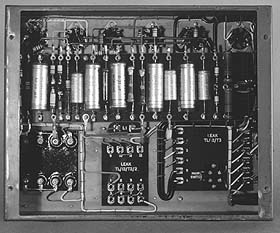
Under chassis view of the TL/12 Power Amplifier. IRON-CORED COMPONENTS.
The mains transformer, output transformer and choke follow first-class design principles. Lamination thickness is 0.014" and the higlh-grade iron has a maximum core loss of 1.25 Watts per kilogramme. (B = 10,000 at 50 c/s). Winding materials and methods are impeccable, and the cheeked bobbins are vacuum impregnated. The coil and core assemblies are strongly clamped on all edges and further safeguarded by varnish dipping. All leads are terminated on soldering tags mounted on engraved panels of tropical-grade material, and the tags appear inside the chassis. The output transformer is symmetrically wound on twin bobbins, and the mains transformer primary winding is electrostatically screened. The appearance of the components is in keeping with performance. American users, particularly, are impressed with the massive construction and exceptional cool-running of these components.
CHASSIS.
This is constructed of 16 gauge (1/16") silver-finished steel. All joints are gas-welded, ground fine, and then surfcaed, after which the chassis is rust-proofed by zinc plating and passivating. The final processing is unusually thorough, and is tabulated below: -
1. One coat of primer, stoved.
2. First coat of finishing, permanent bronze, stoved.
3. Second coat of finishing, permanent bronze, stoved.
4. Lettering by the silk-screen process, air-dried.
5. Final coat of transparent lacquer, stoved.The finished chassis is extremely strong, rust-proof, of handsome appearance, indelibly lettered, and resistant to abrasion.
The bottom short edges carry hank-bushes for securing a baseplate. Type BP/F is the same size as the bottom of the chassis and is primarily intended for use when the amplifier is to be portable. Type BP/O overlaps on the two short sides and carries grommets throughll screws or bolts may be passed for securing the amplifier to cabinet.
HIGH-VOLTAGE CAPACITORS.
These are paper types, fully tropicalised, rated for 600V D.C. working, and manufactured especially to our order. These capacitors are three times as expensive as electrolytic capacitors of similar capacity and voltage rating; unlike the latter, they have an indefinitely long life.
THE GROUP BOARD.
This is of tropical grade, and carries tropically-finishedcapacitors and resistors. It will be noticed that all components are securely fixed and not suspended by the wiring.
TERMINATIONS.All valve-holders are tropical grade Amphenol. The socket terminating the input terminals and the H.T. and L.T. feeds whicll go to the pre-amplifier and or radio unit is also Amphenol. On the right-hand side of the chassis are mounted the protected fuse holder, mains voltage selector, mains outlet socket for gramophone motor, lead-out grommet (optionally, mains switch). the three-pin sunk socket and protected plug for mains and earth connections, and the two-pin sunk socket and protected plug for loudspeaker connections. The mains switch terminal block is fitted inside the chassis so that a twin lead may be run from it, through the lead-out grommet, to terminate at the mains switch in the RC/PA/U pre-amplifier. A mains switch can be fitted on the chassis within four minutes, the grommet hole being used for this purpose.
GENERAL.
The wiring is carried out in colour-coded P.V.C. - covered wire of tropical rating, preformed on jigs, and laced where necessary. Resin-cored solder of high tin contnet is used for all connections, and as we do not allow any form of soldering paste or fluid to be used, delayed faults due to corrosion or degeneration of insulation by spattering of flux cannot occur. All the fixing bolts are of adequate size in cadnium tempered steel.
The photograph giving an under-chassis view shows the apparent simplicity of the wiring and the uncrowded appearance of the components. An unusual design feature is that any component may be removed and replaced without disturbing any other component. It may be of interest to remark that this result is the natural consequence of a layout deliberately contrived to obtain the highest standard of performance and to save time (and therefore labour costs) during assembly and wiring.
It is appropriate here to mention one of the basic principles of LEAK design. From long experience and by extreme attention to design details during development work on the pre-production models, we enable our labour force to achieve a high output per man-hour. The labour costs thus saved offset the increased costs incurred for high-grade materials, components and finishes, and this together with quantity production (made possible only by a worldwide market) explains how quality products may be sold at reasonable prices.
TEST.
Final inspection, as well as testing, is carried out in two laboratories by high-salaried technicians. Each amplifier must pass not only the published performance figures, but other strict tests of our own devising.
For 17 years we have been engaged in designing and manufacturing audio amplifiers for the leading electrical organisations, Government research and Services departments, and the communications industries, and we have never had an amplifier rejected for failing to fulfil electronic performance specifications.
The TL/25A 25 Watt Amplifier
The TL/25A, which supersedes the TL/25, is a modification of the TL/12, the differences being: -
1. The output valves are connected as tetrodes to give 25 watts output.
2. A larger output transformer is used, and feedback is taken from a tertiary winding.
3. An additional valve controls the screen supplies.
4. The bias circuits are modified.Distortion is greater than in the TL/12, being approximately 0.2% at 1000 c/s for 20 watts output, and the damping factor is lower. Gain and frequency response are approximately the same.
RC/PA/U Remote Control Pre-Amplifier
A Leak two-stage tone control amplifier of negligibly low distortion in which resonant circuits or resonant filters are not used. It is designed for use only with Leak power amplifiers, to which it connects by a 3 ft. multiple cable. This unit is a complete re-design, electronically, of the original RC/PA pre-amplifier and of the modified versions supplied to the U.S. market during the past year. The RC/PA/U ('U' for ' Universal') will meet world conditions of use, and it embodies not only the best features of the previous models but every refinement suggested to us by users in Britain and the U.S. in addition to facilities considered desirable by ourselves.
It is only because the TL/12 power amplifier is unique in its combination of high sensitivity, low distortion and unconditional stability that it is possible to design and manufacture a pre-amplifer with the wide facilities and the excellent performance of the RC/PA/U, and to market it at so low a price.
SPECIFICATION: RC/PA/U PRE-AMPLIFIER
Input Facilities
There are three pairs of input terminals, marked " Microphone," " Pickup," and " Radio," one side of each pair being common. These terminals accept inputs from:
(1) Microphone (or other source) of any impedance.
(2) Pickup of any impedance.
(3) Radio receiver (or other source) of any impedance.Input Control
A five-position switch allows the choice of inputs from:
" MIC," microphone (or other source). Response, level.
" LP," long-playing records, with builtin equalisation for Columbia (U.S.) and the new Decca ("London") characteristics. (See note in script re RCA-Victor 45's).
" 78B," 78 r.p.m. records, with built-in equalisation for British characteristics.
" 78A," 78 r.p.m. records, with built-in equalisation for American characteristics.
" RADIO," radio (or other source). Response, level.
Input Impedance and Sensitivities (at 1000 c/s)
The figures given for sensitivity are the 1000 c/s voltages required at the input terminals of the RC/PA/U to give 10 watts output (from the associated TL/12 power amplifier) with both tone-controls in the " Level" positions. Total harmonic distortion in the preamplifier does not exceed 0.02% under these conditions.
" MIC," 200,00.0 ohms, 3mV r.m.s.
" LP," 100,000 ohms, 15mV r.m.s.
" 78B," 100,000 ohms, 1/ mV r.m.s.
"78A," 100,000 ohms, 17mV r.m.s.
" RADIO." 100.000 ohms, 50mV r.m.s.
Frequency Response
The accompanying diagrams show the frequency response curves obtained by measurement across the loudspeaker terminals of the TL/12 power amplifier when it is connected to the RC/PA/U by the 3ft. multiple cable, with the volume control at " Maximum" position and both tone controls at " Level."
Treble Control
A seven position switch allows the choice of accurately determined treble boosts and losses on all inputs.
Bass Control
A seven position switch allows the choice of accurately determined bass boosts and losses on all inputs
Volume Control with A.C. on-off Switch
This component permits switching of the remotely placed TL/12 power amplifier.
Panel Light
This is fitted as a visual reminder that the power is on.
Power Supplies
Heater and anode supplies for the preamplifier are provided from the TL/12 or TL/25A power amplifier through the multiple interconnecting cable.
Spare Supplies
A socket marked " To Radio " is fitted to the pre-amplifier from which the following supplies can be drawn:
Heater, 6.3V, 1.3A A.C. H.T., 440V, 30mA D.C.
Valve
ECC 40 twin-triode.Dimensions
Front panel, 10 3/4" x 3 1/2" (27.3 x 8.9 cms).
Chassis, 10"x3"x2 3/4" high (25.4 x 7.6 x 7.0 cms).Weight
4 Ibs. 8 offs. (2.04 kgs).
This pre-amplifier is of unique physical and electronic design, and no comparable unit is available in Britain (late 1951). It is small and light, and it may be fixed at any angle and in any convenient location by means of its elegant front panel. For instance, mounted on the motor-board of a radio-gramophone or phonograph cabinet, it leaves ample room for motor, pickup, and radio unit, with the advantage of short connections to the latter two components. In this instance the relatively bulky and heavy TL/12 power amplifier can stand in its logical position on the bottom of the cabinet, where it is well away from sensitive input devices such as pickups, input transformers and radio units.
The mains switch incorporated in the volume control enables the TL/12 amplifier to be switched on via a lead brought from the mains switch terminal block mounted within the TL/12. This lead and its plug are supplied with the pre-amplifier.
The RC/PA/U pre-amplifier is functionally complete. It does not need external boxes for equalising networks, filters, selector switches, etc., all of which cost money, take up space, and are troublesome to fix. The RC/PA/U does not magically dispense with these necessities; they are embodied within the pre-amplifier for every input. The cost of the RC/PA/U is therefore the only cost which the user has to find in order to avail himself of the exceptionally comprehensive facilities detailed in these pages. Furthermore, no restrictive conditions have to be placed on the user's choice of pickups because of inadequacies of pre-amplifier design. For instance, the user can choose and use any pickup available in Britain or the U.S. (or likely to lie available in the future). This is because the RC/PA/U has very high sensitivity - 6 times, or 16db, higher than some British pre-amplifiers - and because it is not restrictive as regards the impedance presented by a pickup.
Circuitry:
The pre-amplifier contains a miniature twin triode valve with negative voltage feedback applied to each stage. As the second stage has to provide an output of only 150mV r.m.s. in order to load the TL/12 amplifier the distortion is extremely small, and the negative voltage feedback applied over this stage decreases the initially low distortion. The first stage of the twin triode valve has to provide only the tiny signal of 40mV r.m.s. in order to load the second stage, and the initial minute amount of distortion from the first stage is reduced by negative voltage feedback, just as in the case of the second stage. The feedback is applied to both stages in a manner which reduces the input and output impedances to a few thousand ohms, and these low values bring two major advantages: exceptional freedom from hum pickup within the valve, and a very level frequency response.
An amplifier designer has perforce to start at the output stage and work back to the input circuits. It is therefore logical to describe the second stage of this pre-amplifier before considering the first stage and the input circuits. This second stage embraces the tone-controls, and because these operate on negative feedback principles the distortion is considerably less than with conventional circuits.
Treble loss is accomplished by successive increases of feedback at high frequencies, a method which decreases distortion, whereas the conventional method of shunting a valve by capacitors tends to increase distortion owing to reduction of the load impedance of the valve. Treble boost is effected by switching capacitors across a resistor in the grid circuit which pads out the low input impedance mentioned above.
Bass loss is obtained through resistor-capacitor networks in the output circuit, feedback being fully maintained. Bass boost is accomplished by partial releases of feedback at low frequencies.
The desirability of closely controlled slopes for the shaping networks of the tonecontrol system leaves no choice other than that of step-position switches. This method is clearly more expensive in materials and in labour costs than the use of carbon-track variable resistors, but it is the method always used in studio apparatus such as film and disk recording amplifiers and broadcast station equipment. One of the requirements of a tone-control system is that it must give a level response, as well as variations of bass and treble. Because carbon-track controls have considerable tolerance margins they cannot be accurately marked in a middle position; hence the common subterfuge of covering the true level positions by a broad indefinite marking, usually by the breadth of the words "Level" or "Normal". Continuously variable controls may possibly appear attractive to the amateur at first sight, but they are excluded from the highest grades of apparatus for the reason given above and because they fail to give slopes of optimum shape at all settings, apart from the considerations that they cause more trouble than good switches and have a shorter life.
The finer points of the tone control circuit design will be fully appreciated by professional audio engineers, who will realise from the schematic and from the frequency response curves that a basic assumption during design was that associated equipment of reasonably good performance would be used in conjunction with the RC/PA/U. It will he particularly noted that ridiculously high degrees of bass boost and treble boost have not been made available for misuse. The less experienced should note that an inadequately baffled loudspeaker cannot be made to produce undistorted low notes by increased bass boost because the coil will be driven partially out of the gap to the accompaniment of odd harmonic distortion (Ref20). A loudspeaker seriously deficient in treble response cannot be " corrected" by increased treble boost without the certainty of selective harmonic distortions (Ref 21). If it is found that the bass or treble controls of the RC/PA/U pre-amplifier have to be set in the maximum boost positions when reproducing at normal sound intensity it can be taken as axiomatic that there is a serious deficiency elsewhere in the reproducing chain, e.g., the receiver, pickup, microphone or loudspeaker. The maximum bass boost position may possibly be used when reproducing music very quietly, as may happen in an apartment late at night, for it is well known that the low frequency sensitivity of the ear decreases disproportionately with decreasing sound intensity (Ref 22). This is the only reason for the incorporation of the final bass boost position.
Fig. 2. TONE CONTROLS
These boosts and losses are available on all inputs. On 'Microphone' input
the treble boosts are slightly less.
We can now revert to the first stage and the input circuits. The feedback on this stage is automatically varied when the input selector switch is operated, the variation being suited to the nature of the selected input source. Thus, on the three positions for " RECORDS " the feedback operates selectively with frequency to give the equalisation curves of Figs. 3, 4 and 5. When switched to "RADIO" very heavy feedback is applied and the response is level to 20,000 c/s. On "MICROPHONE " the degree of feedback is reduced in order to raise the gain so that low-level microphones may be used. The frequency response remains level to 20,000 c/s.
Record Reproduction.
The service and instruction sheets give information on
the best method of connecting all types of pickups, and some of the most
popular British and American makes are specifically dealt with.
Figure 3: BUILT-IN L.P.
EQUALISATION
The " LP " position gives an equalisation which is the inverse of the new Decca ("London") and the Columbia (U.S.) long-playing recording characteristics, for these two companies now use almost identical recording characteristics. RCA-Victor 45 r.p.m. records have a similar frequency response above 1,000 c/s, but below 1,000 c/s they require additional bass rise, which may be obtained by advancing the bass tone control .
Figure 4: BUILT-IN
EQUALISATION
for British 78 r.p.m. records.
The "78B" position gives a turnover exactly correct for H.M.V. and Columbia (British) records. H.M.V. recommend that their unworn records he played with treble attenuation (Ref 23), and from a comprehensive experience we recommend a cut of 6db at 10,000 c/s. This amount of treble attenuation is accordingly incorporated in the equalising networks embodied in the " 78B " position. Therefore, most users will find that they will play new H.M.V. and Columbia (British) records with the treble control at " Level," which leaves available an additional boost of 10db or loss of lldb at 10,000 c/s, as required. The Decca characteristic is similar to H.M.V.'s except for a rise above 8,000 c/s. Theoretically it might be expected that for new Decca records one would require to set the " Treble " control at "-1," but in practice this has rarely been found necessary.
Figure 4: BUILT-IN
EQUALISATION
for American 78 r.p.m. records.
The " 78A " position gives an equalisation suited to the majority of American records, as will be seen from the curves of Fig. 5. Differences between various makers' recording characteristics can be compensated by adjusting the tone controls.
When playing worn records the treble loss positions of the tone control should be operated to give the most pleasing balance between surface noise ("needle scratch") and musical content. These loss positions have slopes (rates of attenuation) which are additive to the attenuations introduced by the input equalising networks, but the total slope cannot exceed 10db per octave over any part of the audible spectrum, and there is therefore no danger of " ringing " from the transient mutilation caused by sharp cut-off filters. It is common knowledge among communications engineers that any device having a steep slope of attenuation commencing well within the passband and (say up to 9,000 c/s) will cause transient mutilation. Oscillograms of these mutilations are given by Beranek (Ref 24). For these reasons we, in common with most communications engineers, do not like to incorporate steep-slope filters in highfidelity apparatus. For the minority who treasure old and/or badly worn records we can supply a steep-slope filter as a separate plug-in unit. To some ears the transient mutilation thus introduced is less annoying than the distortions inherent in old and worn records.
Ideally, when playing records at normal volume, the tone controls would he left in the " Level " positions. Unfortunately, records, pickups, and loudspeakers are not yet ideal, and rooms vary in acoustic properties. Consequently the tone controls should be used with discrimination, i.e., they should be set to give the result most nearly in accord with the listener's recollection of a live performance.
Whenever possible, we recommend that pickups should be unequalised when used with the RC/PA/U, so that by using the equalising circuits in the pre-amplifier advantage is taken of the resulting improvement in signal/noise ratio. If, however, users have pickups with associated equalisers, and these are difficult to remove, the output should be taken to the " Microphone" input terminals, instead of to the " Pickup " terminals, in order to avoid the double correction which would otherwise occur.
We have stated that the RC/PA/U pre-amplifier will load the TL/12 power amplifier from any pickup generally available in Britain or the U.S. Some readers may be puzzled in view of the fact that one or two U.S. pickups are rated by their makers as having an output of about 12mV r.m.s. from a particular constant-frequency test record. Such records are always cut at a level at least 10db below the levels which are usual on commercial records, which would therefore give an output of at least 36mV r.m.s. As this voltage is more than twice that required for 10 watts output from the power amplifier there will be considerable gain in hand for the occasional "quiet" record.
Before leaving the topics of record reproduction and pickups we would like to touch upon another point of interest to our American friends, of whom very few will yet have heard a dynamic pickup. The dynamic pickup is free from the inherent nonlinearity of the magnetic types, and the improvement is very clearly audible, just as in the case of the two principles when applied to loudspeakers. The dynamic pickup is considerably more expensive to fabricate and assemble, and a very good dynamic pick-up seems unlikely to be made by mass-production methods. The Leak Dynamic pickup is recognised in Britain by professional engineers as incomparably superior, and it is used as a standard by pickup manufacturers and by record manufacturers. Tests with the E.M.I. Intermodulation Test Record, 400 c/s + 4,000 c/s, and 60 c/s + 2~000 c/s show that the intermodulation distortion from the Leak Dynamic pickup is 1/4 to 1/30 of that from British and American variable-reluctance (moving iron) pickups. Further information will be given in a treatise being prepared by the author.
Radio Reproduction.
American tuner units usually have built-in power supplies, and it is only necessary to connect the output of the tuner to the terminals of the RC/PA/U pre-amplifier.
British tuners usually require an external source of supply for anodes and heaters, and these supplies may be drawn from the socket on the pre-amplifier marked "To Radio". Leak tuner units, when supplied for use with Leak amplifiers, can he fitted with a multiple cable and a plug to fit the socket on the RC/PA/U, and as this cable also carries the speech output from the radio unit the only connection to be made is to the aerial.
The tone controls of the RC/PA/U pre-amplifier will be found invaluable for compensating radio transmission deficiencies. Fuller information on the connection of tuner units is contained in the service and instruction sheets.
Microphone Reproduction.
When reproducing music from a high grade microphone it will probably be found that neither tone control need be moved away from the "Level" positions, though adjustment should be made, if necessary, to suit room acoustics and the loudspeaker characteristics.
When reproducing the voice from close proximity to a velocity microphone it will be found desirable to cut bass, for reasons which are well known (Ref 25).
Startling realism (literally, and in no exaggerated sense) is obtained when reproduction from high grade microphones such as the S.T.C. 4033A (W.E. 639A in the U.S.). This microphone together with the pre-amplifier, the TL/12 power amplifier, and the Leak ' 550 ' loudspeaker, is the combination used by H. J. Leak in his demonstrations of sound reproduction to technicians and music lovers (Ref 26). At these demonstrations the audience first hears an orchestra reproduced from an adjacent room and then (within two minutes) hears the orchestra performing before them in the lecture theatre. This direct comparison test of the goodness of a reproducing system requires amplifiers of exceptionally low distortion.
Disk Recording.
When recording on disk, bass cut and treble boost will probably be used in magnitudes mainly dependent on the characteristics of the cutter-head. Cutter-heads having a flat high-frequency characteristic may need additional treble boost if it is desired to record at increased velocities in the upper register, and this boost may be obtained by a resistor-capacitor network before the pre-amplifier. One of the leading British recording companies inserts a complete equalising network between the output transformer of the TL/12 and their cutter-head. This method is possible only when the cutter-head requires a maximum power of approximately 2 watts.
The recordist using the RC/PA/U pre-amplifier with the TL/12 power amplifier has the assurance that his total amplifier distortions are as low as those prevailing in the foremost recording studios of the world.
Film Reproduction, l6 mm. and 35 mm.
The phototube output should be taken to the "Microphone" input terminals. Polarising potential may be obtained from the radio supply socket on the pre-amplifier. Full details are given in the instruction sheets. When used with high efficiency horn-loaded dual loudspeaker systems the RC/PA/U plus TL/12 combination provides highly satisfactory volume and quality in theatres seating up to 1100. For a seating capacity of 1100-2200 we recommend the use of the TL/25A amplifier, though the output power required is always dependent upon theatre acoustics and layout, and upon loudspeaker efficiency and distribution.
The multiple cable connecting the RC/PA/U pre-amplifier to the TL/12 power amplifier is standardised at 3 ft., and complete with plugs is included in the price of the pre-amplifier. At an extra cost, longer cables can be supplied up to a maximum of 16 feet, which length increases the loss at 20,000 c/s to 3 db.
The RC/PA/U pre-amplifier has been designed specifically to feed the TL/12, TL/25A or other suitable Leak equipment, and it is not intended for use with other amplifiers. There are two main reasons for this decision. First, almost all power amplifiers require at least 1V r.m.s. for full output, as compared with 0.15V r.m.s. for the TL/12. Second, we do not wish the pre-amplifier to be used with power amplifiers having insufficient margins of stability, or which are not in other respects comparable with the TL/12. We are compelled to restrict the sale of the RC/PA/U to users of the Leak power amplifiers, for only in this way can we ensure that the fine performance of this pre-amplifier will be maintained.
The RC/PA/U matches the TL/12 in finish, which is bronze with cream lettering and knobs.
The RC/PA/U and TL/12 amplifiers are drilled and tapped so that the units may be bolted together within two minutes to form a compact P.A. amplifier. Three modifications are made to the RC/PA/U for use in this manner: a short cable link, type CL/S, and a non-overlapping front panel, type FP/F, are supplied, and a bracket holding three 3-pin sockets for the inputs is fitted on the top left hand deck. A top cover with a carrying handle, type TC/L, can be supplied to fit over both units, an entry being left for the three input plugs.
We have a very wide experience of modifying the amplifiers herein described to suit special requirements. As examples, meter switching can be incorporated and a variety of panel mountings have been arranged. Please do not hesitate to let us know your physical requirements. Kindly note that modifications are undertaken only on minimum orders of 50 amplifiers of one type.
References
1. F. E. Terman. "Radio Engineering," 3rd ed.,
pp. 311-314.
2. H. W. Bode. "Network Analysis and Feedback Amplifier Design,"
p. 32.
3. " Cathode Ray." " Wireless World," May, 1946.
4. H. J. Reich. " Theory and Applications of Electron Tubes,"
p. 223.
5. F. E. Ternman. " Radio Engineers' Handbook," p. 474.
6. H. J. Reich. " Theory and Applications of Electron Tubes,"
p. 659.
7. F. E. Ternman. " Radio Engineers' Handbook," p. 474.
8. H. J. Leak. " Sound Recording,'' Vol. 3, No. 3, 1948.
9. D.E.L. Shorter. "Electronic Engineering," April, 1950.
10. H.W. Bode. "Network Analysis and Feedback Amplifier Design,"
p 454
11. C.F. Brockelsby. "Wireless Engineer," Feb. 1949.
12. F. Langford Smith. "Wireless World," Feb. 9/16th, 1939.
13. Keith Henney. "Radio Engineering Handhook," p. 926
14. J. Moir. "Wireless World," May, 1950.
15. H. S. Black. '' Bell System Tech. Journal.'' January, 1934.
16. H. J. Leak & Co Ltd. "Journal Brit. I.R.E.," Sept 1945.
(First "POINT ONE" advertisement in the technical press).
17. H. W. Bode. '"Network Analysis and Feedback Amplifier Design,"
p478.
18. H. W. Bode. '"Network Analysis and Feedback Amplifier Design,"
p453.
19. H. W. Bode. '"Network Analysis and Feedback Amplifier Design,"
p41.
20. H. F. Olson. '' Elements of Acoustical Engineering," 2nd. ed, p
201.
21. F. Langford Smith. '' Radio Designer's Handbook," p. 69.
22. L. L. Berenak, '' Acoustic Measurements,'' p 200.
23. E.M.I. Ltd. Brochure of Technical Data. ''Lightweight Pickup No. 12".
24. L. L. Beranek. Acoustic Measurements.'' pp 413, 417.
25. H. F. Olson. ''Elements of Acoustical Engineering," 2nd. ed. p.256.
26. H. J. Leak. '' Wireless World," April. 1950.
Editorial account of lecture to, British Sound Recording Association.
Historical Note
We were the first manufacturers in the world to design and advertise amplifiers with a distortion content as low as 0.1%, hence the adoption of " POINT ONE " as our trade mark. The 1945 advertisement referred to (Ref 16) stated, " these figures establish such radically new standards that they may occasion some surprise. We therefore wish to stress that no error appears in this announcement." Many people duly expressed surprise and incredulity, but communications establishments with laboratories equipped for accurate measurement placed large orders after making technical investigation. The length of the lead we established can he accurately placed from a survey of technical publications from 1945 onwards.
After some time our performance figures earned wide acceptance, partly through the circulation of comfirmatory reports by independent laboratories, and partly because the broad principles of feedback amplifier design were explained in technical journals of wide circulation. This spreading of knowledge brought the realisation that the new performance standards which we claimed were in fact obtainable provided scientific methods of design, and control of production, were employed.
We then had to face the contention that our amplifiers need not be so good as we had made them in view of the distortions existing in microphones, records, pickups and loudspeakers. That this contention is no longer held (at least, in Britain) owes something to the comparative demonstrations given by H. J. Leak to technical audiences and individual engineers, and to the consistently superior audible results obtained by users of "POINT ONE" amplifiers. It had to he faced, however, that the production of these amplifiers with such desirable characteristics was relatively expensive.
In 1948 the problem of costly production was surmounted when we abandoned our original 4-stage circuit of 1945 for the simpler, more sensitive and completely stable 3-stage circuit of the TL/12.
The basic TL/12 circuit was evolved in 1947 by H. J. Leak for use with feedback cutter-heads, and the circuit was so stable that feedback magnitudes greater than 40db could be obtained over the loop containing the three stages, the output transformer and the electro-mechanical circuit of the cutter-head. We realised that with this new circuit we had the opportunity of offering a superlative amplifier, but with our high-grade labour it was essential to use the most advanced techniques of manufacture and to ensure quantity production if the price was to be kept low. We knew that the very large orders necessary for quantity production would come only if the amplifier gained world-wide acceptance from three main classes of users:
2. The non-technical music-lover or gramophile.
3. The knowledgeable amateur enthusiast (the "audio hobbyist" of the U.S.) who had previously built his own amplifiers for reasons of economy and/or personal satisfaction.
With these requirements before us further development work was carried out on the basic circuit and on the physical details, and the TL/12 in its present form was launched in December 1948, together with the RC/PA pre-amplifier.
Today, late 1951, it is well known that our projects of three years ago have proved successful, and that the RC/PA and TL/12 amplifiers have a prestige and market that is world-wide. During 1951 to date orders totalling over 2,000 have been received from the U.S.A. for RC/PA/U and TL/12 amplifiers for high quality radio/gramophone reproducers for the home.
The professional engineer who places bulk orders knows that every amplifier meets its specification, and that the other requirements for his class of equipment - reliability, accessibility, craftsmanship, finish and appearance - are successfully met.
The non-technical music-lover (guided by advice and demonstrations from his music shop, radio retailer, jobber or custom-set builder) knows that he has chosen reliable amplifiers of convenient form which look better, sound better, and stay that way: a satisfying and economical solution of his quest for perfection.
There is no doubt whatever that the growth of understanding of the enormous improvements obtainable from first-grade feedback amplifiers has been paralleled with the appreciation that they are complex scientific instruments and that the specialist designer and manufacturer of such instruments has advantages (in experience, " know-how " and facilities) which for obvious reasons cannot possibly be acquired by the amateur. The discriminating amateur enthusiast has therefore patronised us with rapidly increasing support, not only by entrusting to us the supply of his own equipment, but by recommending our products to his non-technical friends.
TL/12
12 Watt Amplifier with valves and plugs(Please state output load impedance adjustment you require)
TL/25A
25 Watt Amplifier with valves and plugs(Please state output load impedance adjustment you require)
Optional Facilities
Fitting 1250 Watt Mains Switch to TL/12 or TL/25A..........
Fitting 100,00 ohms volume control and input jack with plug to TL/12 or TL/25A. (Only when used without the RC/PA/U)..........
Flush Baseplate, type BP/F..........
Overlapping Baseplate, type BP/O..........
Top Cover of RC/PA/U for bolting to TL/12 or TL/25A amplifiers, complete with non-overlapping front panel, type FP/F; short multiple cable, type CL/S; and bracket complete with three input plugs and sockets..........
Top Cover, type TC/L, to enclose both RC/PA/U and power amplifier, complete with carrying handle and entry point for input plugs..........
Supplying and fitting mu-metal cased input bridging transformer to TL/12 (as for the B.B.C.)..........
Supplying steep-slope filter in mu-metal case, with cut-offs at 6kc/s, 8kc/s and 10kc/s. Complete with lead and socket for plugging into the RC/PA/U...........
The TL/12 and TL/25A amplifiers whether supplied alone or with the RC/PA/U pre-amplifier are packed in a strong returnable case for which a charge of 30/- is made. This charge is refunded in full on our receipt of the case. All prices are ex-works.
Each amplifier is accompanied by detailed circuit drawings showing values of components and voltage and current data. Physical layout drawings are also supplied. Advice is given on the use and connection of microphones, pickups, radio units, and loudspeakers and on the method of adjusting the output transformer connections for various loudspeaker impedances.
Designers and manufacturers of: -
Audio frequency amplifiers for all purposes up to 1,000 watts output.
High fidelity loudspeakers.
High fidelity moving-coil pickups.
Complete Public Address installations.
High fidelity radio receiver units.
Suppliers to: -
Government Departments and Research Laboratories. The L.C.C. and Local Government Authorities.
Broadcasting Companies in many countries.
The B.B.C.
The Sound Film Industry.
The leading Telephone Companies.
The Shipping Industry.
The leading Gramophone Recording Companies.
| Telephone: SHEpherds Bush 1173/1174. |
Telegrams: |
