 |
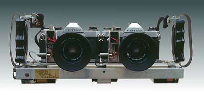
| Figure 1: Twin Rig Stereo Camera Based on Pentax K1000 Cameras |

| |
| Figure 1: Twin Rig Stereo Camera Based on Pentax K1000 Cameras |
The twin stereo rig presents the possibility of enormous flexibility to the stereographer. It allows the photographer to vary at will the lens focal length, and the distance between the cameras. Used in the right circumstance, the a twin rig with the right focal length, and appropriate camera separation can make a normally uninteresting stereo photo into a striking one. It does however require some knowledge of the various depth distortions that are introduced when the camera configuration departs from that required for ortho-stereo (base=65mm, and lens focal length equal to that of the stereo hand viewer). In addition it also requires an appreciation of the allowable "on-film" deviation and how to avoid exceeding it.
The primary focus of this paper is to describe the method of firing the shutters of the two cameras simultaneously, although other aspects of lenses and physical mounting are also covered in less detail.
Many SLR camera are candidates for use as a twin stereo rig. In fact some modern cameras have an electronic input for firing the shutter, and so firing two cameras simultaneously for stereo becomes quite easy (provided adequate synchronization can be assured). This paper describes the use of two older SLR cameras (Pentax K1000) that have a mechanical shutter, and mechanical shutter release. Variants of this model have also been used (SP1000, SP500 which are cheaper again as they have the older style screw-mount lens base).
The K-mount (bayonet) lenses that have been used with this twin rig range from: 17mm Tokina rectilinear wide angle; 28mm Pentax; 35mm Pentax; 50mm Pentax; 105mm Pentax; 135mm Pentax, and also a pair of A-series 35-105mm zooms. In all cases adequate matching of focal lengths was obtained with out testing the lenses (expect for the 17mm Tokina's which were possibly on the limit of acceptable matching - say more than 2% different). The use of zooms is attractive, but highly impractical, and not recommended, as it is virtually impossible to set them for equal focal length.
The bar used for mounting the two cameras is a U-section of aluminium extrusion. The size of the extrusion was chosen so that the batteries and firing capacitor could fit snugly inside the U-section. The U-section has been inverted, and a pair of camera flash-brackets with handle grips have been mounted on top . The cameras mount to these flash brackets as normal.
This arrangement was used as a prototype configuration, which has stayed that way. It would be better to arrange for a more positive method to locate the cameras - the flash bracket unfortunately allow the cameras to rotate (toe-in or toe-out) if an eye isn't kept on the alignment. It is very undesirable to have the cameras toe-in for stereo. So the best twin rig mount would include some sort of edge to locate the camera bodies on the bar so they are always held parallel.
If required, a longer bar can be made that has various mounting points for the cameras, so that the camera base can be varied. For wider separations it is necessary to remove one camera from the twin-rig and place it on a tripod to align the two cameras (or alternatively, have a partner hold the other camera - once you agree on an alignment point in the scene).
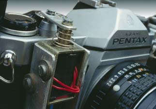 |
| Figure 2: Solenoid & Linkage to the Shutter Release |
Twin cable release can be used for initial twin-rig experimentation purposes, however it will soon be found that the synchronization is inconsistent.
The Pentax K1000 has a mechanical shutter release, and requires about 4 Newtons (say 400grams) of force to release it. The system described here uses a small 12 Volt solenoid on mounted on each camera body to release the shutter. An aluminium bracket can be made that connects to the body using the pair of existing 2mm screws in the base of the camera as the only mounting point to the body - the solenoid is in turn connected to the aluminium bracket, and position as shown in Figure 2 just in front of the shutter release.
The solenoid used in this case was supply by "Radio Spares" (a large U.K. - based electronics supplier), and was catalog number 347-652, (rated at 12Volts continuously, or 38Volts for 10% duty cycle). The solenoid has a 3mm tapped hole in the end of the plunger, and a flat piece of 1.6mm aluminium was made to link this end of the plunger to the shutter. The connection of the linkage to the plugger is firm, but the connect to the shutter release is loose (a slot was cut in the linkage, and a 3mm screw used in to cable release merely to hold the link over the button - but not tightly otherwise the solenoid will bind. Figure 2 also just shows a sleeve of blue plastic (stripped from some wire) placed over the "tail" of the plugger - this was done so that the plunger cannot fall out of the solenoid if the screw into the cable release comes adrift.
To obtain the necessary force from the solenoid to release the shutter, it was found necessary to exceed the voltage rating of 12V. There is no harm in doing this as the applied voltage is sustained for less than 0.5 seconds in the system described (which has been in use for since 1986). It is also possible to get better synchronization between the to cameras if the solenoids actuate faster.
As a result of these considerations, the solenoid is driven from a capacitor of 10,000 microFarads which is charge up to 36 Volts over a period of a few seconds before each exposure. (The capacitor-discharge principal is very similar to that used to fire the older type of bulb flash units.) A circuit is shown in Figure 3.
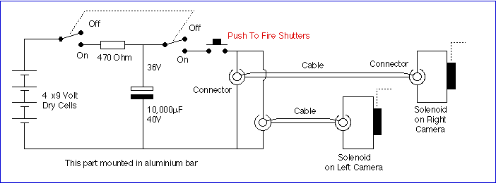 |
| Figure 3: Circuit of the solenoid shutter release |